| |
 |
|
The 33rd Annual Running Of the very popular University Of Oxford Digital Signal Processing Course will be held online.
Weekly Lessons: Monday 17th April to Friday 17th May 2023.
Classes are held live, online, on Wednesday afternoons and are recorded for repeat viewing.
|
|
| |
 |
|
V10.0 of the SigLib DSP Library released. Full Details Here.
The full SigLib DSP and ML Library can now be downloaded from GitHub.
See our SigLib Introductory Video to learn how to use the library.
|
|
| |
 |
|
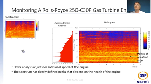
At this year's DSP Online conference John Edwards presented Building A Tensorflow Lite Neural Network Vibration Classifier, With A Little Help From DSP. The presentations for the 2022 DSP Online Conference are recorded and available for streaming even if you register after the event has concluded. |
|
| |
 |
|
John Edwards presented a tinyML Talk on December 22, 2020
"Low MIPS & Memory Machine Learning Industrial Vibration Monitoring Solution -
AKA Not All AI Applications Are Cat v Dogs on Facebook ;-)"
View The Presentation And Download The Code Here. |
|
| |
 |
|
Read our "eBook: 8 DSP Fundamentals Every Electronics Engineer Should Know."
Written in conjunction with Dunstan Power from ByteSnap Design. |
|
| |
 |
|
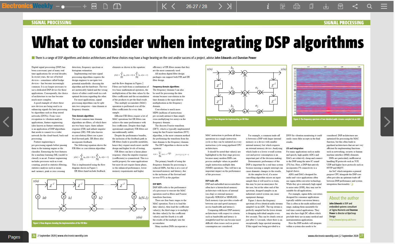
Read our "What To Consider When Integrating DSP Algorithms" article in the Sept 1st 2020 edition of Electronics Weekly.
Written in conjunction with Dunstan Power from ByteSnap Design. |
|
| |
 |
|
The Data Science Festival 2020 presentation entitled
"The Frequency Domain And How It Can Be Used To Aid Artificial Intelligence" was presented by John Edwards. Click Here To View. |
|
| |
 |
|
At the 2021 DSP Online conference John Edwards presented An Introduction To High Efficiency And Multi-rate Digital Filters. The presentations for the 2021 DSP Online Conference are recorded and available for streaming even if you register for this year's event. |
|
| |
 |
|
At the 2020 DSP Online conference John Edwards presented Frequency Domain Signal Processing. The presentations for the 2020 DSP Online Conference are recorded and available for streaming even if you register for this year's event. |
|
